
Suggestions for a build
There is a National Technical Specification for Gravity Racers in the UK. If you build to this then you have entry to the British national open events. Do double check that you comply with the Australian local events.
Wheels
We have the best going.
I can supply just hubs in future if you can get them made up. These only take about 10 days to send by air.
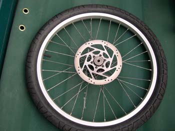
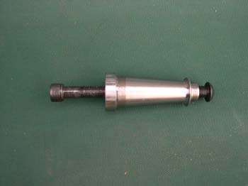
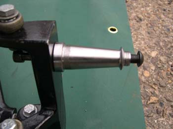
Unlike bikes, gravity racer wheels need to be able to take a sideways force. To get the best you need to think about the width of the hub. Ours is 10mm wider than others. The sturdiness of the rim and the number of spokes. We have 48 spokes. You also need to attach the wheel from one side so you will need a wide stub axle which will not bend or break.
If you can enclose the wheels your speed will increase.
Before we started to make our own wheels we were using Cannondale hubs and getting them made up. Cost £600 for four!! They were not as good as ours. We were cornering on hairpin bends in Germany at 50 MPH. No problems. No buckles.
Tyres are important as air friction is increased with tread. You only need tread for wet. We usually only run in the dry so we have smooth ‘slick’ tyres. We do take a set of tyres with tread as well in case of rain. Again make sure that you have the correct width of tyre, 35 mm is usual, but sometimes event regulations may differ. Despite the theory that tyres should be at 120 psi to reduce friction, we have found that 80 psi is the optimum because the energy is absorbed in giving you good road handling and speed rather than shaking your teeth out of your skull.
You might like to change the grease in the bearings for a light oil. You can remove the outer bearing covers with a Stanley knife.
If you can enclose the wheels your speed will increase. If you can not then just enclose the spokes.
Tyres are important as air friction is increased with tread. We usually only run in the dry so we have smooth tyres. We do take a set of tyres with tread as well. Again make sure that you have the correct width of tyre, 35 mm is usual but sometimes event regulations may be different from National Technical Specifications.
Despite the theory that tyres should be at 120 psi to reduce friction, we have found that 60 psi is the optimum because the energy is absorbed in giving you good road handling and speed rather than shaking your teeth out of your skull.
If you have active suspension then 120 psi would be good.
To line up wheels we use fishing line tied to marks between our front and rear bumpers. Well if the system is used by Formula 1 then we should be OK with it!
I can supply just hubs in future if you can get them made up. These only take about 10 days to send by air.
Unlike bikes, gravity racer wheels need to be able to take a sideways force. To get the best you need to think about the width of the hub. Ours is 10mm wider than others. The sturdiness of the rim and the number of spokes. We have 48 spokes. You also need to attach the wheel from one side so you will need a wide stub axle which will not bend or break.
If you can enclose the wheels your speed will increase.
Before we started to make our own wheels we were using Cannondale hubs and getting them made up. Cost £600 for four!! They were not as good as ours. We were cornering on hairpin bends in Germany at 50 MPH. No problems. No buckles.
Tyres are important as air friction is increased with tread. You only need tread for wet. We usually only run in the dry so we have smooth ‘slick’ tyres. We do take a set of tyres with tread as well in case of rain. Again make sure that you have the correct width of tyre, 35 mm is usual, but sometimes event regulations may differ. Despite the theory that tyres should be at 120 psi to reduce friction, we have found that 80 psi is the optimum because the energy is absorbed in giving you good road handling and speed rather than shaking your teeth out of your skull.
You might like to change the grease in the bearings for a light oil. You can remove the outer bearing covers with a Stanley knife.
If you can enclose the wheels your speed will increase. If you can not then just enclose the spokes.
Tyres are important as air friction is increased with tread. We usually only run in the dry so we have smooth tyres. We do take a set of tyres with tread as well. Again make sure that you have the correct width of tyre, 35 mm is usual but sometimes event regulations may be different from National Technical Specifications.
Despite the theory that tyres should be at 120 psi to reduce friction, we have found that 60 psi is the optimum because the energy is absorbed in giving you good road handling and speed rather than shaking your teeth out of your skull.
If you have active suspension then 120 psi would be good.
To line up wheels we use fishing line tied to marks between our front and rear bumpers. Well if the system is used by Formula 1 then we should be OK with it!
Suspension
Assuming that you are using our alloy cast parts. If buffed up these look incredible. A quick way is to use fine steel wool and then a good metal polish.
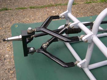
To attach these to the frame use 10 mm male rose bearings (already in place).
Adjust the length of the rose bearing screw thread into the suspension parts to adjust the suspension geometry. Make sure that you use lock nuts all around.
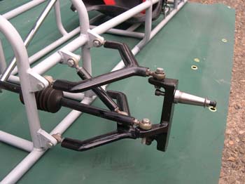
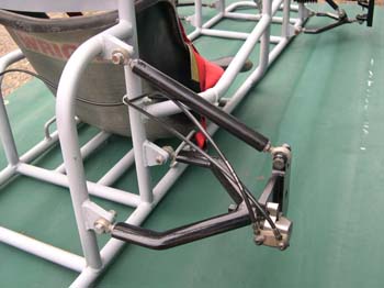
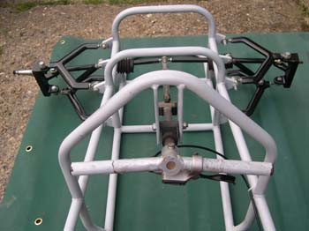
Our design has a suspension bar from the wishbones to the spaceframe. We have used the same system as the steering arms with solid metal rods and left and right hand thread rose bearings. The rear ones are 205 mm and the front are 125 mm long. These allow us to easily adjust the weight on each wheel and also the height of the vehicle by turning the rods.
The caster angle has been set at 8 degrees. This gives better steering control.
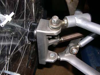
To attach the rear wishbone to the rear upright we have had professional aluminium welding. The rear upright is welded to the totally flat side including the plate to attach the callipers. For added strength we have drilled a bole to take a 10mm bolt to hold on the upright. This needs to be drilled and tapped.
If you wish to construct your own suspension units we have already done this with steel. Contact us for photos of our system.
To attach these to the frame use 10 mm male rose bearings (already in place).
Adjust the length of the rose bearing screw thread into the suspension parts to adjust the suspension geometry. Make sure that you use lock nuts all around.
Our design has a suspension bar from the wishbones to the spaceframe. We have used the same system as the steering arms with solid metal rods and left and right hand thread rose bearings. The rear ones are 205 mm and the front are 125 mm long. These allow us to easily adjust the weight on each wheel and also the height of the vehicle by turning the rods.
The caster angle has been set at 8 degrees. This gives better steering control.
To attach the rear wishbone to the rear upright we have had professional aluminium welding. The rear upright is welded to the totally flat side including the plate to attach the callipers. For added strength we have drilled a bole to take a 10mm bolt to hold on the upright. This needs to be drilled and tapped.
If you wish to construct your own suspension units we have already done this with steel. Contact us for photos of our system.
Suspension parts advice
Our suspension parts are designed for education projects. Therefore you might like to work on their looks. Buffing up will make them look really nice.
They are made from cast and toughened aluminium alloy. The rear upright is rolled aluminium. We weld them together which has always served us well. If you are intending extreme punishment on this part we have drilled a 10mm hole that you can then carry on drilling, then tap and die for an extra retaining bolt if you wish.
We drill and then tap and die to take a 10mm rod end if needed.
The rear uprights will take bike callipers for braking. (We can supply)
The bottom front wishbones have been cast so that they can be used either way up. We leave them like that leaving the extra lugs on in case we ever break them. Then they can be removed and put back the other way up on the other side of the racer!
Please make sure that washers are used next to the alloy castings.
We do put markings on the suspension parts when we send them out.
These note which part goes where. Also we put APPROX positions for drilling holes. Please measure where you need to drill exactly as our markings are only an indication.
Steering
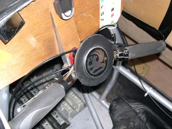
The column has a screw bolt on the bottom. This is inserted into a rose bearing that has already been bolted onto the plate on the spaceframe. The screw bolt is then put into the rose bearing and secured with a lock nut.
The top of the column is secured by a nylon bush onto the two mounting brackets on the spaceframe. These mounting brackets point upwards.
Bolt on the steering handle so it is closest to the driver.
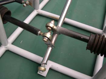
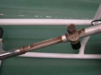
To attach the steering arms we have welded two 50 mm steel uprights onto the column. These are exactly two rose bearings apart. We have drilled a 10 mm hole through these uprights 35 mm from the column. Bolt the two rose bearings in place so that you can attach the steering arms. It is best to put the left hand thread rose bearings next to the steering arms. We do not put lock nuts on these as they are hard to get to at an event. We do put lock nuts on the other end.
By attaching the rose bearings 35 mm from the column we achieved a 1:2 ratio with the arm on the front uprights which was 70 mm long.
Our steering arms were made of solid steel rods. We attached male 10 mm rose bearings each end by drilling and taping. We put in a left and a right hand screw thread on so that we could adjust the length, and hence toe in or out, by just turning the steering arm.
The top of the column is secured by a nylon bush onto the two mounting brackets on the spaceframe. These mounting brackets point upwards.
Bolt on the steering handle so it is closest to the driver.
To attach the steering arms we have welded two 50 mm steel uprights onto the column. These are exactly two rose bearings apart. We have drilled a 10 mm hole through these uprights 35 mm from the column. Bolt the two rose bearings in place so that you can attach the steering arms. It is best to put the left hand thread rose bearings next to the steering arms. We do not put lock nuts on these as they are hard to get to at an event. We do put lock nuts on the other end.
By attaching the rose bearings 35 mm from the column we achieved a 1:2 ratio with the arm on the front uprights which was 70 mm long.
Our steering arms were made of solid steel rods. We attached male 10 mm rose bearings each end by drilling and taping. We put in a left and a right hand screw thread on so that we could adjust the length, and hence toe in or out, by just turning the steering arm.
The spaceframe

Ideally plastic coating is good, but in schools or colleges if it is damaged it is hard to patch up. We have used undercoat and an enamel spray that can be easily touched up if needed.
One of the latest requirements is a tow hitch on the front so that you can be towed up hills at events by rope.
One of the latest requirements is a tow hitch on the front so that you can be towed up hills at events by rope.
Seat
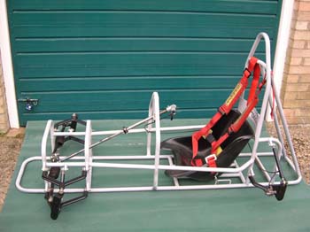
The frame is designed to take a go cart seat. Bolt it to the steel tubes on the floor. The back of the seat should be just under the welded back support. But we usually sit our driver in and then move the seat around until he / she is most comfortably. Hence no holes drilled. Use large washers.
Your driver will be grateful for a little padding duck taped into the bottom. Do not tighten the retaining bolts up too tight as it might split the seat.
Your driver will be grateful for a little padding duck taped into the bottom. Do not tighten the retaining bolts up too tight as it might split the seat.
Safety Belt
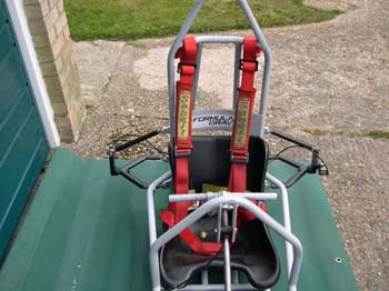
We use a four point seat belt. There are floor mounts on the space frame on the side of the seat. You might like to use a screw chain link to fix the belt onto. The rear strap goes under the floor strut behind the seat. Do make sure you have left a gap so that you can get the belt between the strut and the floor. (I missed this once and had to take half the racer to bits!!!) Make sure that there are no buckles on the collar bone area of the driver. These should be worn tight. Tighten the lap belt first.
The floor
This needs to be strong as we attached our weights to this. We used aluminium sheet. It could be curved up at the sides. We put the spaceframe onto a sheet, drew around it and then cut it out using a jig saw. (Tin snips were used to trim up). 37cms x 193cms.
The spaceframe was turned upside down and we drilled and then pot riveted about every 100 mms. Using 4mm drill bits and rivets. (We used this size through out the build) To finish we used a hammer to bend the outside of the floor around the tube frame. Do leave space under the back floor strut to feed through the rear strap to the seat belt!!!
(Check event rules for weight regulations. We have found that weights are best with their centre of gravity about a third of the way from the front. This gives better steering and grip on corners.)
Brakes
The rear uprights have a plate to fix the rear brake callipers. I have already fixed on your brakes. We use bike brakes. All bike brakes are fixed the same side so all the rear brakes fix on the same side. You can not get left and right hand brakes. So one plate faces back and one faces front.
Despite the theory that all bike brakes are manufactured to fit on the same mountings they do not! We therefore make the plate on the upright a bit larger than needed and cut and drill to size.
Front and rear callipers are also different fixing measurements. We therefore buy two sets each time and marry up brakes so that a racer either has front or rear brakes attached to keep each racers brakes uniform.
I have marked your two sets of brakes accordingly. A small ‘F’ and ‘R’ sticker on the calliper as well.
Brakes depend upon budget. You can spend a lot on money on these and not get a better performance. (We get a set two for £20) Shimano will cost more than £200.
Remember that with the surface area of your tyres on the road brakes are only to retard speed. If you lock your wheels you will destroy your tyres and then loose control. (We tried it)
As yet brakes in the UK are only required on one axle. This might change next year.
Generally our racers are scrutineered at events by having to hold against a 50Kg pull. but check event technical specifications. We put our brakes on the rear so that you retain steering if you lock them up. Front brakes are easily put on by attaching a steel plate on the front upright. We did this for our German mountain run.
Hydraulic brakes have given us problems with the plastic hydraulic pipes expanding especially in summer leaving us with spongy brakes. If you do want hydraulic in the future, we suggest metal brake pipes.
We have gone for wire bike brakes operated from the steering wheel. I have included cable ties to secure the brake wires into the frame. No sharp corners for the cables. Check steering handle and cable freedom.
Bodywork
A well designed and finished racer is everything. This is as important at an event as winning it.
You need to research streamlining and style together with materials. There are new materials becoming available all the time.
We build from 1.5 mm beech plywood or aluminium.
We found that beech wood ply is best cut by using a small hand held angle grinder with a narrow disc. This avoided the jagged edges of a saw and was very quick. We also used tin snips. These were indispensable.
To make the patterns we used brown paper or newspaper. This was good to also get the left and right sides the same.
To attach the wood to the steel tube we first use a broad head self drilling screw using a hand held battery drill with a Phillips screw head. This helps stop the wood splintering and splitting. It is also quick. When the body work is in place remove each screw one by one and replaced them with countersunk 4 mm pot rivets about every 50 mms. To join body work sheets use rivets again with washers on the inside. When the body is finished use car filler to cover over all joins and then used primer and spray as normal. The finish is as good as a car.
If you have sponsors ask for stickers for the racer. These also cover up scratches etc.
Before putting the body work onto the racer you could stick on some black vinyl on the inside so that it looks really nice inside as well. We did this by using spray adhesive.
Our canopy is edged in aluminium cut out from a sheet and riveted on. This stops the plastic from splitting.
If you are enclosing your driver you must allow the driver to open the canopy and get out by themselves. i.e. you can not screw them in. We used Velcro.
Nerf Bars and Bumpers
These may be required if the event is running racers together.
Nerf bars are located between the wheels on the side of the racers. These prevent other racers getting their wheels entangled in yours. These would not be needed if your body work covers these areas and is strong enough.
We sometimes attached bumper ‘horns’ to the front of our racer as some events need these. These were bolted to the front suspension mounts. Our side nerf bars we welded on to the side of the space frame, and the rear bar was bolted on to the roll bar.
Instruments
A bicycle Speedo is really needed. The radio wireless Speedos do not work as the distance is too great from the wheels to the dash board. I have supplied a wire controlled Speedo. You will need to cut the wire and add a bit of wire in to go the distance.
You can make a nice small dash board mounted on the two struts that hold the steering column. Mount the speedo onto this. If you are really flash a sat nav will also be great. Blue tooth mobile phone can also give you communications. We are looking into further innovations in this area.
RACE SET UP (We check this before any race)
Once you have built the racer up you will need to adjust the wheels. We have found that they go best if they are straight up. You can bring the top of the rear wheels in a bit if you like the look.
Adjust the length of the rose bearing threads in the suspension parts to achieve this. Then tighten the lock nuts. (Not too tight)
The wheels need to be set in a straight line. For easy quick we use a straight piece of wood. This is put against the wheels on each side to get them straight. Adjusted by rose bearings on the back and by turning the steering arms on the front. ( Do not forget the lock nuts on the front steering arms.) Remember the front and rear wheels might not be exactly the same distance apart across the axles.
Some teams just use a garage laser system.
Now you need to adjust the wheel heights. The racer should sit on a level floor with the steering straight ahead. Bathroom scales under each front wheel should read the same. If not twist the front suspension support rod that has a rose bearing at each end after loosening the lock nuts. As there is a left and right had thread on this rod, this will raise or lower the suspension and hence the wheel.
Adjust until both wheels are pushing down with the same weight.
Now check it all again!
Drivers kit
Full face helmet.
Karting neck brace.
Good gloves
No bare skin
Finally do check entry technical specification and racing rules for any event that you are entering. These may change year on year.
Phone me if you have any problems. UK 01284 830428
I suggest you build then phone for a quick chat.
Health & Safety
Needless to say Health and Safety during the build is paramount. Some parts of the build you may need to get professionally done. If you are in any doubt check first with your school / college regulations. We would also be pleased to help with your Health and Safety requirements.
Finally do check entry technical specification and racing rules for any event that you are entering. These may change year on year.
Finally do check entry technical specification and racing rules for any event that you are entering. These may change year on year.